Previous: Day 3 – Gertboard Setup
Configuring Motor Controller
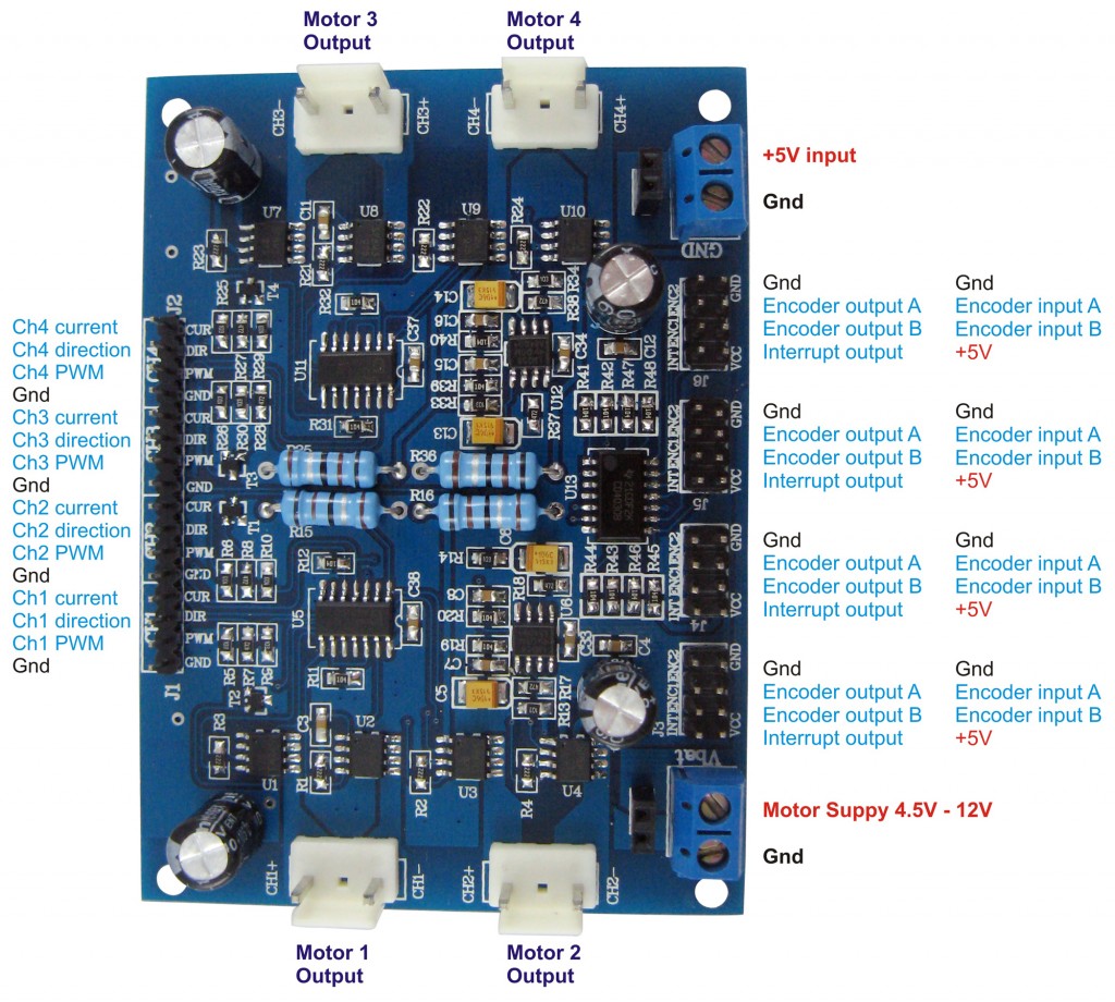
At LinuxCircle we are happy with Dagu 4-Channel Motor Controller Board. Connect each motor to its corresponding motor ouput. Prepare 8 jumper wires for the micro controller pins to be connected to your Gertboard and 4 jumper wires to your current supply pins. You need 2 power supplies to go into the “Motor Supply” socket and the “Logic 5V input” socket.

Each channel is controlled by the black control pin on the left hand side of the above picture.
- CUR is for power, but at this stage just leave them blank, because we want to power the board via its Motor Supply connector.
- DIR is for controlling the motor backward or forward, any digital pin will do.
- PWM must be connected digital PWM pin of the Gertboard.
- GND is where you connect to Gertboard common ground.
To setup a full throttle forward:
- DIR must set to HIGH
- PWM must be set to 255
To stop:
- DIR can be either HIGH or LOW
- PWM must be set to 0
To move backward:
- DIR must be LOW
- PWM must be set to 255
Next: Day 5 – Power Supplies
(Visited 1,996 times, 1 visits today)
2 thoughts on “Robot Project Day 4 – Motor Controller”
Comments are closed.


I need to correct 1 item on this instruction set since I have been using this motor controller for my robots as well. In the section you describe the motor control pins. You list pwm, dir, gnd, and cur. ‘CUR’ is not for powering the motors, it is for monitoring the power usage of each motor. Each channel can handle 5 amps max. (4 safely). This pin would be read by an analog pin on the gertboard or arduino to detect things like a motor stall and allow your code to change direction or shut down the motor. This is useful if your robot gets stuck on an undetected obstacle which would cause the motors to pull too many amps to the board/motor.. Another tool to automate your robot.
The ‘motor supply’ is the power used for all motors. The other power pins on the upper right are for regulated 5 volt supply for the ‘logic’ (brains) of the board. It allows a clean/controlled supply for the logic part and then a separate , higher current supply for the motors which will spike quickly due to the motor usage.
Both of these supply line gnds as well as a 4 motor channel gnds should be connected to the gertboard and controller gnds (gertboard is already connected to the Raspberry Pi gnd). Everything should share a common ground. It is not enough just for the power supplies to share the gnd. The 4 motor channels themselves must be connected separately or you will get some strange behavior from the motors (no directional control). It’s a bug that is very hard to locate since the motors still function ‘forward’.
The dagu 4 channel controller is unique and is really my favorite since it has so many features even if the documentation is lacking.
Excellent review! Thanks for sharing with us!