This tutorial will show you how to have the basic servo control using Raspberry Pi and Pololu Maestro. The implementation of the following instruction can be used for hand gripper, robot leg, or pan/tilt camera.
Hardware list:
- Raspberry Pi Model A 256MB
- Pololu Maestro USB 6-Channel Servo Controller
- MG946R Towardpro servo (or similar)
- Power supply: 1300mAh 11.1V LiPo baterry
- UBEC 5V 5A with the right connectors
- A laptop running Ubuntu or Mint
- 4 leads with different colours: Black, Red, Blue, and Yellow
- SD Card 8GB loaded with Rasbian OS
- USB Wifi Dongle
- Raspberry Pi power supply or USB to microUSB lead to power it up with your laptop USB
- Wireless Router
Software list on the Pi:
- Rasbian
- Pololu manufacturer driver and application supplied for initial testing purpose
- Pololu Python3 driver (you can code your own, or modify someone else’s)
- CherryPy or Tornado web server installed for Python3
- Client side codes: JQuery, HTML5, CSS
- SSH access enabled
- Wifi connection enabled
Setting Up the Pi
Insert the SD card, insert the USB Wifi dongle, connect the power, and make sure you can boot and SSH into the Pi from your laptop. There are many tutorials on how to do this, will not be covered on this note.
Turn off and power off Pi before you connect any peripherals.
Setting Up Pololu Maestro
There are 3 components to be connected with the Maestro:
- Raspberry Pi
- Servo(s)
- Power line
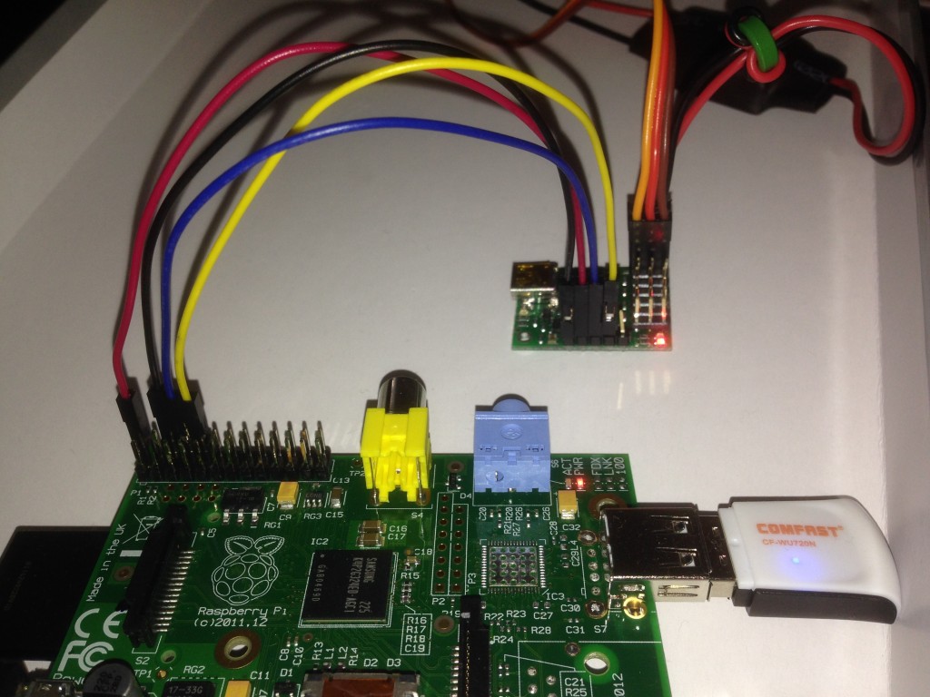
1. Pololu Maestro – Raspberry Pi GPIO wires setup:
- Connect Pi GPIO 5v pin with red wire to Pololu Maestro VIN pin
- Connect Pi GPIO ground pin with black wire to Pololu Maestro GND pin
- Connect Pi GPIO TX pin with blue wire to Pololu Maestro RX pin
- Connect Pi GPIO RX pin with yellow wire to Pololu Maestro TX pin

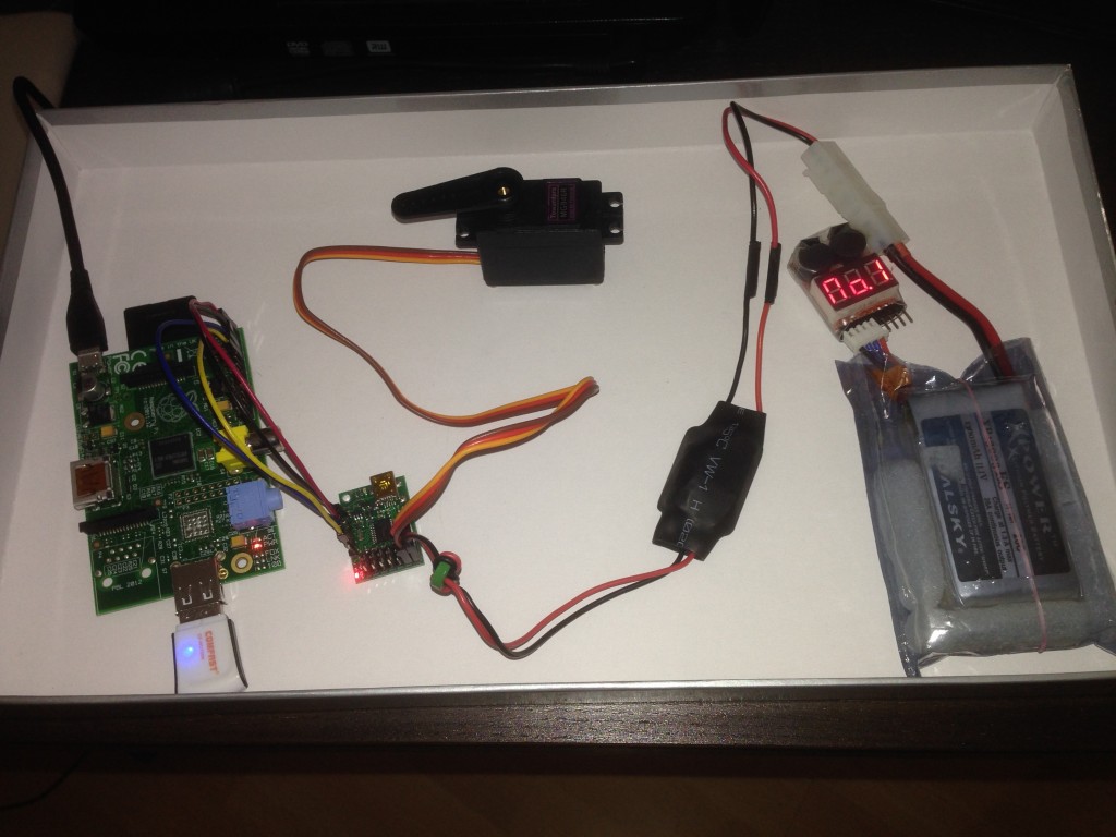
2. Pololu Maestro – Servo setup:
- For a start, please use Mid-size servo like MGR946R or any servo with similar spec
- Connect servo wires respectively with the following channel 0 pins on Maestro: SIG, PWR, GND
- To connect more servos, you can use any of the remaining channels 1-5.
3. Pololu Maestro – Power setup:
- Pololu Maestro accepts 5V power input for the control circuit, so Pi GPIO 5V pin is sufficient for this purpose.
- Pololu Maestro relays whatever power you supply for the servos. In this exercise, 11.1V LiPo battery connected and voltage-converted via UBEC 5V 5A is perfect to power up to six servos. A typical mid-size servo will run on 5V-6V and use up to 1A under a heavy load. Please check your servo spec before connecting any power.
See below picture for complete setup
Software Architecture
Let’s prepare the basic building blocks to control a servo via the Internet. For this you must be familiar with basic Python3 codes, HTML5, and JQuery.
A simplistic view of the application connectivities are as follows:
Client-side controller interface -> Python 3 Web Server (Via CherryPi or Tornado WebSocket) -> Python Driver – > Servo
Pololu Maestro Python 3 Driver
The following Python 3 driver can work for basic servo tasks: Device.py. Feel free to modify it to suit your needs. This is an open-source public property. If you could come up with awesome improvement to the Driver, don’t forget to upload it on GitHub and share it with all of us.
To test if it works, you can download and run this Device-tester.py file for basic servo sweeping command.
2 thoughts on “Raspberry Pi + Pololu Maestro + Python3 + Tornado + Servo Control Part 1”
Comments are closed.


Hi Dipto
I am interested in using Device.py on my servo-driven camera pan & tilt project. I have a Raspberry Pi B+, a Pololu Mini Maestro 24 and an external battery power supply. The Maestro and battery combination works perfectly when connected by USB cable to my Windows laptop, using the Maestro Control Center app and I have successfully controlled the servos in a test sketch on my Arduino.
I have downloaded Device.py and saved it in a dedicated folder on the RasPi. I have connected the RasPi GPIO pins to the designated pins on the Maestro (with the RasPi powered off) and a servo is plugged in to channel 0. I have loaded Device-tester.py into Python3 IDLE.
If I attempt to run the script from within IDLE, the response from within the Python Shell begins:
“could not open port /dev/ttyAMA0: [Errno 13] Permission denied: ‘/dev/ttyAMA0’
Link to Command Port –
/dev/ttyAMA0
-failed”
If I type the command “$ sudo python3 Device-tester.py” from within LXTerminal I get the following (rather satisfying) feedback:
“Link to Command Port –
/dev/ttyAMA0
– successful
Link to TTL Port –
/dev/ttyAMA0
– successful
Device error flags read (
None
) and cleared
Device initialized:
True
servo: 0 value: 5440
Degree =
90
Iteration = 0 . Speed = 5
servo: 0 value: 8000
Degree =
180
Iteration = 1 . Speed = 20
servo: 0 value: 2880
Degree =
0
Iteration = 2 . Speed = 35
servo: 0 value: 8000
Degree =
180
Iteration = 3 . Speed = 50
servo: 0 value: 2880
Degree =
0
Iteration = 4 . Speed = 65
servo: 0 value: 8000
Degree =
180
Iteration = 5 . Speed = 80
servo: 0 value: 2880
Degree =
0
Iteration = 6 . Speed = 95
servo: 0 value: 8000
Degree =
180
Iteration = 7 . Speed = 110
servo: 0 value: 2880
Degree =
0
Iteration = 8 . Speed = 125
servo: 0 value: 8000
Degree =
180
Iteration = 9 . Speed = 140
servo: 0 value: 2880
Degree =
0
conf
”
I should point out I am a complete Raspberry Pi noob; I took delivery of my B+ only last week. It is running the latest Raspian Debian Wheezy.
Can you tell me (if it’s not a stupidly embarrassing question) why I get the error messages from trying to run the script from within IDLE? Apologies if this is too trivial . . .
Thanks for sharing your project; I am looking forward to part 2, although if I can work out the appropriate min & max PWM values for my servos, what you have posted in part 1 will be sufficient for my project.
Looks like IDLE doesn’t have permission also there maybe conflict with Terminal access e.g. screen when you try to open the RX and TX ports of the GPIO. Have you disabled Terminal access via UART?
Have a look at: http://www.irrational.net/2012/04/19/using-the-raspberry-pis-serial-port/